Honest John 1B
This rocket is is a 4-inch sport-scale model of the Honest John 1B. The 1A, with the giant triangular fins, is more commonly modelled, but I prefer the look of the 1B.
This rocket was printed using PETG in an Army green color. The main feature was how I printed wraps to finish the body instead of painting. Not only did this avoid the mess of painting, but it made sure the body matched the color of the printed parts.
The Pictures
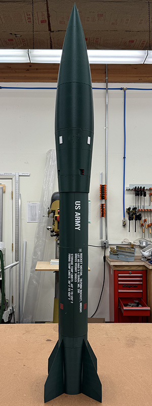
Tony "tfish" Alcocer was kind enough to fly this rocket (and the Nike-Smoke) to test out how 3D printed rockets survive L2 HPR flights.
Flight 1
Tony:
"The shapes of this rocket had me thinking about CG/CP too,
but with the nose cone being big and bulky it might be over stable?
Got it prepped and it seemed fine.
First flight motor was a 38mm 4 grain Research motor similar too an
AT I211.
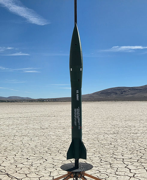
"With the rocket prepped and ready to fly at 103 ounces this flight would be about 7:1 thrust to weight ratio… still no wind…out to the pad. The motor came to life and lifted the HoJo to 1244 feet where the 1+ gram charge did it's job to deploy the 60" flat sheet chute. The 1½ gram charge fired but was not needed. The rocket landed close at 19 ft/sec."
 |
 |
Flight 2
Tony:
"The second flight was prepped just like the first flight.
The motor of choice for this flight was 54mm 3 grain Research motor, similar to the
AT J415W.
Still no wind, but at ignition the rocket left the pad at a 45 degree angle.
It stayed on this course until it reached apogee. At 3015 feet, the deployment charge fired.
I was surprised to see it all hold together. It had some pretty good speed to it when the parachute deployed.
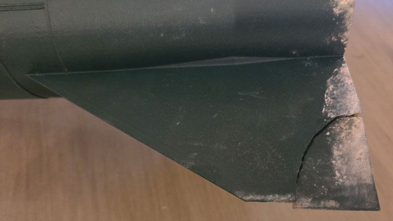
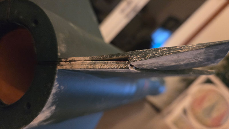
"I hitched a ride with Ken Adams and the rocket was over a mile out. it landed at 24 ft/sec. It ended up with one of the fins corners being broke. This probably happend during the deployment process. It's fixable. Concidering the flight angle and speed during deployment I feel the rocket is pretty durable. The main question is why did it leave the pad at such and angle? CP/CG issue? just one of those things?"
Flight 3
Tony:
"[At Aeronaut 2026] the HoJo flew on a
K550W.
It flew off the away cell due to the non vertical flight on its last flight.
This time it flew perfectly straight to 6143 feet, even with an pretty good wind.
Open landing out on the windy playa, the recovery eye bolt unscrewed from the nut while it was being blown around on the ground.
There was no damage to the rocket. Even the fin to carbon plate repair stood up to the 700ish mph flight.
3D printing has come a long way!"
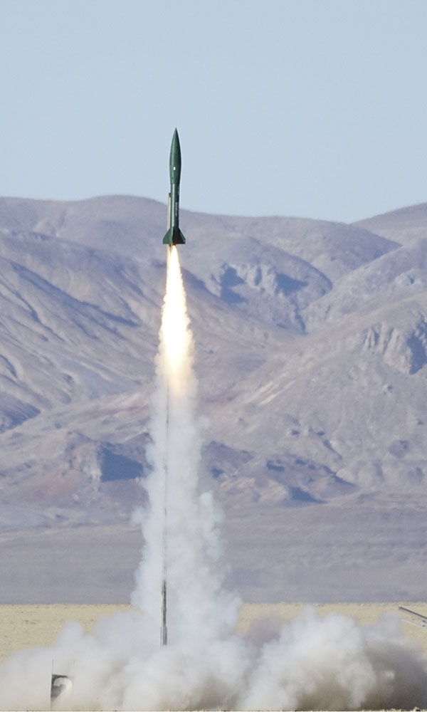
Love that White Lightning smoke and the K550 is one of my favorite motors. Thanks Tony!
Learnings
Learnings from this rocket:
- The CF plate fin inserts seem to have created a week spot, so it's hard to know when reinforcement is necessary and probaly better not to add any until it's clearly needed.
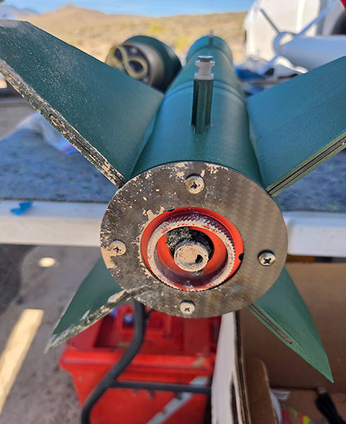
- The plate did indeed protect the aft end from heating due base drag and the fin can showed no obvious heat damage.
- PETG printed parts are fine for I-J motors, which is great news.
The Design
My build uses mostly 3D printed parts, except that I still prefer standard phenolic body and motor mount tubes in most cases. However, using standard body tubes means filling spirals, priming, sanding, and painting. I didn't want to do that, so I came up with the idea of trying printed wraps, which turned out pretty well.
Of course, I couldn't print the wrap as a single part, so I split it into four pieces. There were longitudinal panel lines on the prototype, which I could take advantage of for the front/back split. However, there weren't panel lines that would camoflague the forward/aft split. In retrospect, I should have invented panel lines there to make it look more intentional.
My first attempt was a single filament layer using a 0.4mm nozzle. That worked, but was cruder than I like and so had some small holes at the corner of lettering. The final wraps were printed with the finest possible settings using a 0.2mm nozzle with 3 layers. The bottom layer was all the background color (green) and the white lettering and red squares were 2 layers thick. Using the minimum layer height, this made the wraps still flexible enough for a 4"e; tube and opaque.
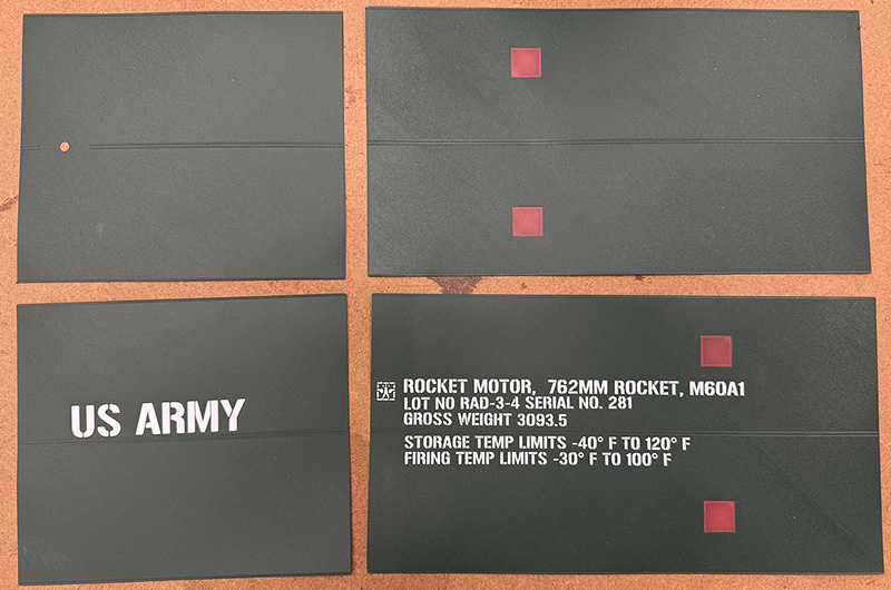
In case anyone wants to do something similar, here are the printed parts:
- nose base
- nose mid
- nose tip
- fin can
- forward CR
- ebay gasket
- ebay insert
- ebay ring
- wrap back aft
- wrap back fwd
- wrap front aft
- wrap front fwd
Or one zip file of them all. Or you can download them from Thingiverse.
The CR and ebay were printed in PLA-CF, the body sections in PETG and the gasket in TPU. I always use gyroid infill with the CRs and fin can at 50% to maximize strength and the body parts at 15% to reduce weight.
The wrap is split into four pieces. the front and back along panel lines that exist in the prototype. The lettering is very slightly taller, enough to paint with color in the slicer, but not enough to print taller.