Ariane 6 (A64)
In June 2018, I was completing several long-standing projects for launching in Summer and thought about starting a new project. I'd come off a sequence of open-interstage projects (Aerobee, Iris and Boosted Arcas) and needed something different.
The Ariane 6 A64 is planned to have four strap-on boosters, something I had not yet undertaken, so that seemed perfect for a new challenge.
The Pictures
The Design
The first question with a scale model is always the scale. As usual, I try to come up with a scale that corresponds to available body tube sizes. This rocket also couldn't be too small because I needed space for the drop-away booster mechanism so I wanted to use a 5.5" or larger tube.
At 3% (2.85% to be precise), the main body could be 6" tubing and the boosters could be 3.9" tube couplers:
| Prototype (m) | Model (in) | Model (mm) | |
|---|---|---|---|
| Overall height | 62.0 | 69.6 | 1767 |
| Main AF len | 60.6 | 68.0 | 1721 |
| Main AF Θ | 5.4 | 6.1 | 154 |
| Main nose len | 8.3 | 9.3 | 237 |
| Booster AF Θ | 3.4 | 3.8 | 97 |
| Booster body len | 13.0 | 14.6 | 371 |
| Booster nose len | 13.0 | 14.6 | 371 |
This also makes the rocket a manageable size at 5' 10" (1.8m). See the overall drawing for details.
The aft end is where all the complexity of this rocket is; the forward is just a standard dual-deployment setup with a mid AV bay. So the first thing to work out was how the drop-away boosters would work. Luckily, the design of the prototype could be used pretty much as-is. A side plate near the aft of the boosters would lock against the aft end of the sustainer and the forward strut would slot into the sustainer. Then the only trick was retaining/releasing the boosters.
I decided that the thrust would be transferred through the aft plate and the forward strut was needed only for retention and alignment. That means the only remaining tricky part is how to keep each booster in place until its motor burns out. I decided to use a solenoid, activated by electronics to pin it in place.
I decided to use clear plastic fins for stability (one new thing at a time). Because of the four outboards and needing space for the launch rail, they didn't fit evenly 120° apart, so they're not quite radially symetrical. See the aft detail in the overall drawing.
Construction
This rocket has lots of unusual parts and I relied heavily on 3D printing to make them. I have a Prusa MK3 plus sent some parts out to Sculpteo when they needed to be heat-tolerant.
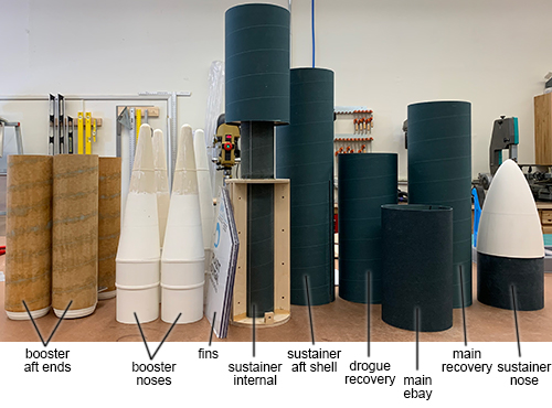
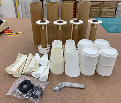
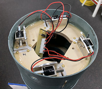
Above you can see the main parts of the rocket in their rough stage, giving an idea of the complexity.
Boosters
The most interesting part was the boosters and how to interfaced with the main rocket, so that's what I started on first. There's lots of great detail: the nose, ribbing along body and the tail.

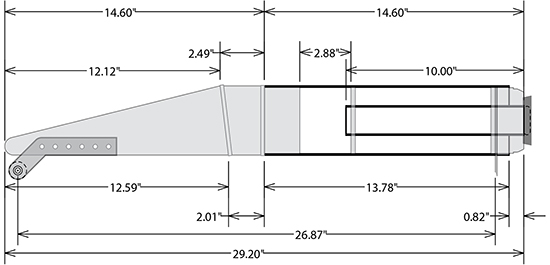
The interior of the boosters was complex. Here is a close-up of one booster from the overall drawing:
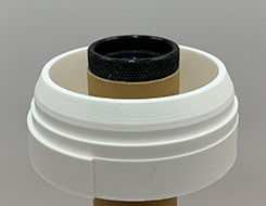
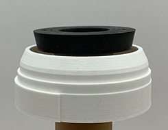
After figuring out the design, I started printing the tail parts. The profiles were PLA, but the retainers (to suggest the nozzles) needed to be more heat-resistant so I had them printed by Sculpteo in Multijet Fusion PA12, which is heat-resistant to 700°C.
Above you can see the four tail end profiles and a PLA prototype of the retainer. And below you can see how the white profile fits around the MMT and the retainer caps it off.
 |
 |
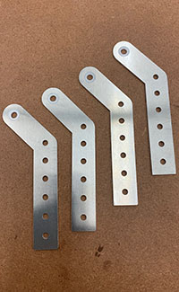
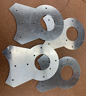
The brackets which attach the booster to the sustainer are aluminum. The forward one (below left) slots into the side of the booster and is retained until dropped. The aft one (below right) presses against the base of the sustainer to transfer the force of the booster motors.
 |
 |
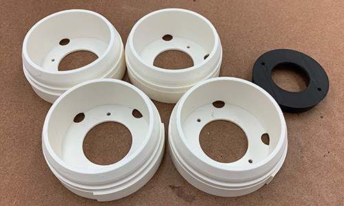
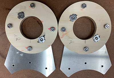
The aft brackets epoxy and bolt to the aft centering rings. Below you can see two of the four assemblies glued up. The T-nuts near the inside are for motor retention, but are being temporarily used for extra clamping while the epoxy cures.
Once the aft bracket were bonded to the aft centering rings, the forward centering rings and after CR assemblies were bonded to the motor mount tubes. Below you can see all four tacked in place and ready for epoxy fillets.
I should have taken a "parts pile" photo first, but here is the pile at the point where the MMT assemblies were bonded and all the 3D printed parts are done. (I started with a white filament and finished with an off-white one, which accounts for the color difference.)
Next I glued up the noses from their four pieces. For more details, see the printing large parts video.
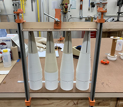
Above you can see the first step with forward brackets sandwiched between the two halves of the tips and bonded into the top of the mid sections. Below is the second step with the forward sections (tips and mid) bonded onto the aft sections (single parts). I clamped them to make sure they were firmly seated and to make them as consistent as possible.
Then it was back to the aft end of the boosters. The first thing was to cut a notch for the aft bracket to protrude. Below you can see the slots coming off the CNC router, with the one on the left trimmed and showing how the MMT assembly fits into the gap.
You can't see it, but I also drilled holes for Nylon screw shear pins and a slot for the alignment of the printed part while the tubes were on the CNC.
Above is a close-up of the aft end after bonding, showing how the slot in the airframe tube is filled with a boss on the printed part.
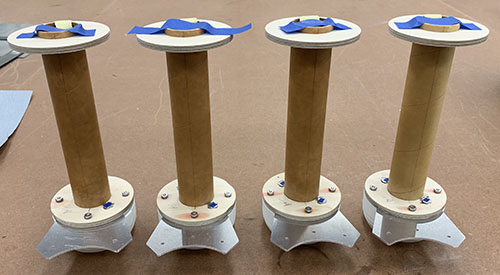
Once all the aft sections were bonded, the booster rough fabrication was complete. Above, the booster are shown rotated successively by 90° so you can see all the details.
And finally my favorite detail is shown above: the 3D printed motor retainer with the angled sides that represents the nozzle of the prototype.
Drop-Away Mechanism
The boosters light before the sustainer, so the thrust from their motors pushes against the base of the sustainer through the aft brackets. The forward brackets slot into the booster airframe and the solenoids are just to prevent them from sliding backwards until the rocket lifts off. Shortly after liftoff, the solenoids unlock and the boosters will hopefully fall away as their motors burn out.
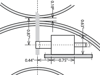
Above is a close-up of the drawing showing how each solenoid retains the hole in the forward bracket. See the full drawing for details.
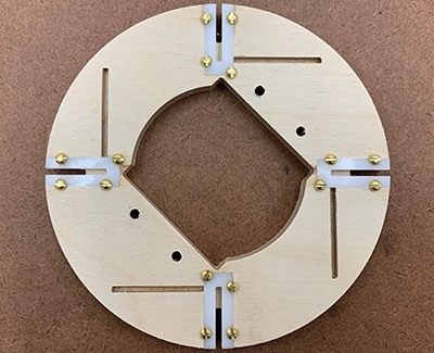
This is the single most complex part; requiring 5 steps of CNC routing operations to make. In order to hold the booster front brackets in alignment with minimal friction, I used acetal plastic plates. The perpendicular slots are for the solenoid brackets (see below).
Here's how the booster forward bracket will insert through the CR in each of the four slots.
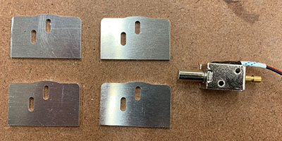
And then the aluminum solenoid brackets. The solenoids came with 2 threaded holes for M3 screws, so that defined the spacing. Note that the holes are elongated to provide some vertical adjustability for later fine tuning.
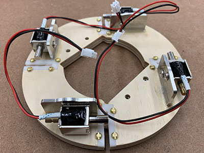
Above you can see the completed locks. The brackets are bonded into the slots in the CR and the solenoids are attached to the brackets with screws. (Actually M3x5 computer motherboard screws as it turns out.)
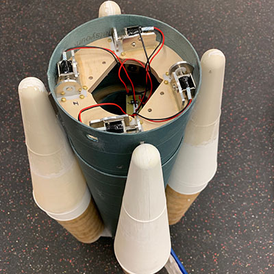
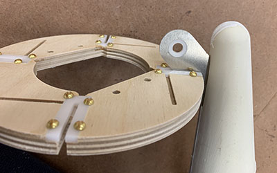
And a test-fit of the boosters slotted through the coupler of the aft section of the booster and engaging with the solenoids. This completes the mechanical part of the drop-away mechanism.
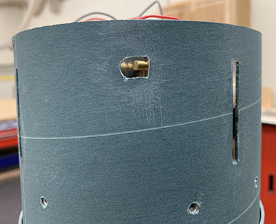
In order to slide the boosters into place, the solenoids have to be released. This side view shows slots for the booster forward brackets and an access hole to release the solenoid manually by pushing the shaft to the side. At the bottom you can see some of the 8 holes that retain the forward airframe which covers this coupler and protects the drop-away mechanism when the rocket is prepped.
The video above shows many more details as well as the mechanism in action.
Nose Cone
The nose cone was a custom shape as well, so I decided to 3D print it, even though it was too large to make in one piece on my 3D printer. I put together a video on printing large parts in multiple pieces.
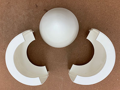
To reduce the amount of printing, I made the shoulder out of a piece of coupler tube. This also has the advantage of providing a more traditional bonding surface for the ring you can see below.
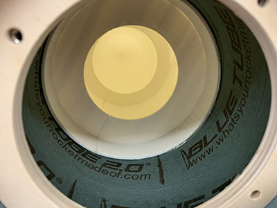
This ring allows a plate to be screwed to the base of the nose, providing a nice bay within for a tracker.
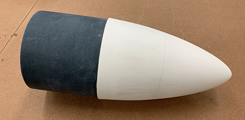
The completed nose cone looks pretty much like any other one you've seen, although it was a lot less work than molding one from fiberglass.
Sustainer
The sustainer is just a 6" rocket, with a standard dual-deployment layout (apogee break mid and low-altitude break forward). See the side view in the overall drawing for details.
The dimensions of the sustainer were constrained by the forward bracket attachment of the boosters, so there is less recovery space than one would expect for a 6" rocket; only 5" for the drogue and 10" for the main. The end caps of the avionics bay are recessed to create a little extra space, but the recovery system will definitely be tightly packed.
Because the prototype has no fins, I decided to build my fins from polycarbonate (clear plastic). Also, because of the four boosters and requiring space for the launch rail, the fins couldn't quite by 12° apart.
 |
 |
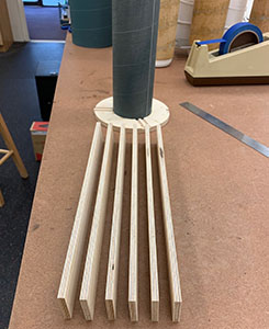
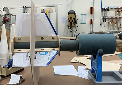
Above you can see the aft end of the motor mount tube with the rear centering ring and the 6 internal ribs to which the plastic fins will bolt and on the right the aft airframe slotted and the MMT assembled. Note that the coupler at the top of the MMT is the booster retention bay.
Cutting fins from polycarbonate is reasonably easy, but you have to use a much lower feed rate and a fresh end mill. The ends can be polished then flamed to near transparency; see my Plastic Fins video for more info.
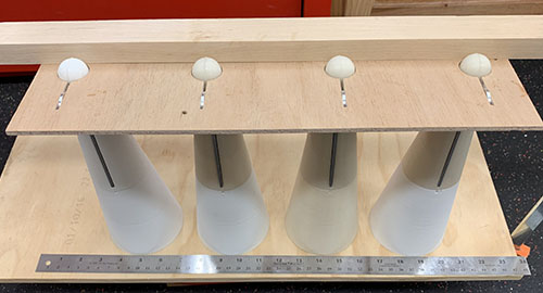
The fins were bolted to the ribs, which were epoxied to the MMT and the centering rings. Above you can see the assembly in a fin guide as the backing T-nut for the forward rail button cures.
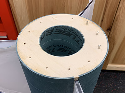
The aft centering ring has holes for pins that align the four boosters. The aft booster brackets push against the aluminum aft plate and register on the pins (3 pins per booster).
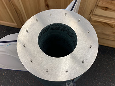
Above you can see the aft end after three pins are installed. After the pins were installed, a 1⁄16" aluminum plate was epoxied on to finish off the aft end. This will take a lot of heat from the motor due to base drag so having a solid surface is good.
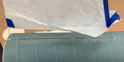
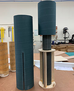
Once the body tube was slipped over the core, the fins disappear, at least in side view. The last step was to fill in the small gap in the fin slots. (And just being careful not to scratch the fins during the remained of construction, which is why I left the film on the fins.)
Once everything was lined up, the ring with the solenoids was mounted inside the coupler at the forward end of the sustainer aft section. This completes the aft section and the mounting for the boosters.
Historical Info.
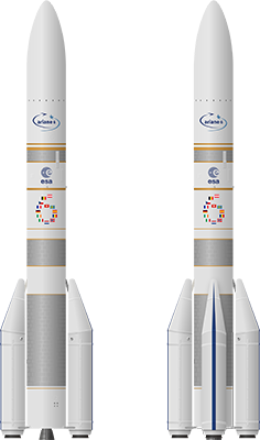
Unusually for me, the prototype rocket is not yet in service. So "history" is a bit of a misnomer. There is good general information on French Wikipedia. There are also some nice 3D renderings for reference.
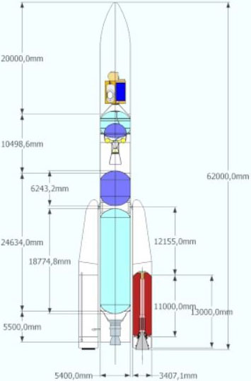
I also found the image above very useful for getting dimensions, even if not complete, thanks to "Crumb fire" on The Rocketry Forum.
The side view above (full size here) was very useful for markings and shapes. Although you will notice there is some variance in the different drawings, especially in the nose of the strap-on boosters. I ended up taking the details from this drawing since it's the most complete.
There's also lots of good info in the Ariane 6 User's Manual.