Light Show
At Aeronaut 2013 (where I flew my Comanche 3), Jim Green flew a great night launch rocket, his "Blinkasaurus Maximus". I hadn't built many night launch rockets (really only the Mosquito Swarm) so it seemed like time to expand my reportoire.
What really sparked this project was talking with a friend at work about his Burning Man project, a sound-controlled shirt using LEDs controlled by an Arduino. After that, some searching and experimentation settled on the basics of my rocket.
I decided to use addressable WS2812B pixel strips, sold by AdaFruit under the name "NeoPixel"), allowing complex light patterns controlled by an Arduino.
The first rocket was destroyed on its first flight, but I always liked the idea so decided to rebuild it in late 2017. Version 2 would be larger in diameter and easier to prep, but keep the same overall appearance.
The Pictures
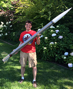
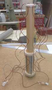
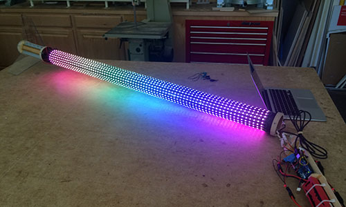
Here are the just-completed pictures of version 1 on July 19, 2014. Normally one shows off a rocket with daylight pictures, but this rocket looks better at night.
 |
 |
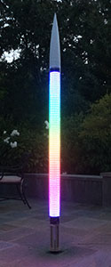 |
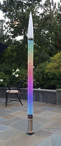
Photographing this rocket is quite hard. The two photos above right are in the dusk (early and late) since at night the lights just wash out the picture. Even with the iPhone HDR setting, it's hard to get a good exposure. Then of course you have to imagine the rainbow is moving along the length of the rocket... (I tried to get video; here's my not-very-successful result.)
XPRS 2014
I had intended to fly the rocket at Aeronaut in August, but electrical problems had forced me to postpone until XPRS in September. The rocket flew Friday, September 12 on an AeroTech J415.
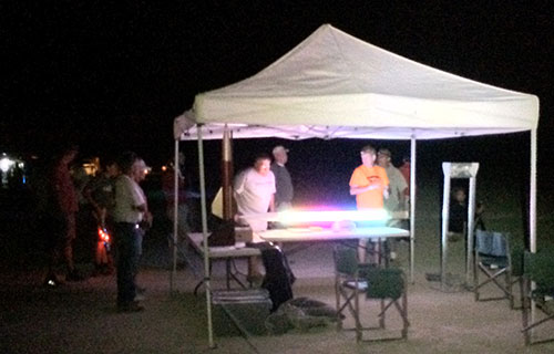
I powered up the light display and brought it out to the RSO table, which immediately attracted a crowd.
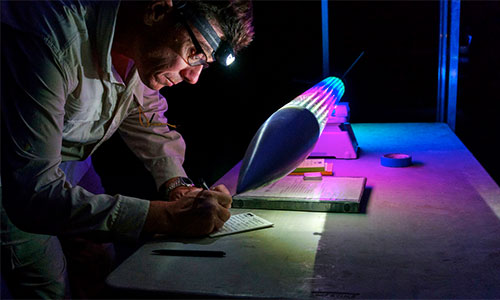
Above you can see the rocket on the scale as I fill out the flight card (picture by Peter Thoeny).
The flight looked good, until apogee when the recovery system failed to deploy. The rocket came in ballistic and smashed to pieces right on the range. (I found the electric match, which hadn't popped, so either continuity was lost or the R-DAS failed to fire it.)

The next morning, I dug out the rocket, buried past the nose cone, and picked up innumerable shards of the Acrylic outer body tube (picture by Peter Thoeny).
The Design
Like Jim's rocket, mine would have an Acrylic® body with LEDs inside. I decided on a 4" O.D. tube (1/8" wall) for the body and standard 3" phenolic tubing for the core struture. The LED strips would be mounted to the surface of the inner structure and the outer tube would slide over after preparation.
A big concern was power to drive the LED pixel strips; each meter draws about 800mA when drawing typical patterns (more if solid white). I wanted the lights to be able to last at least 40 minutes (pre-launch, on the pad, flight and recovery), so that meant that I would have to fly a lot of power.
The pixel strips are 1cm wide (0.4") wide, so the maximum number that could fit on the outside of a 3" tube is 25 (9.9" / 25.1cm outer circumference). I ended up settling on 20 strips due to power concerns (four batteries, driving five strips each) and to leave a little space between strips for wiring and access.
Speaking of batteries, their volume and mass were major considerations in the design. Four 5000mAh R/C car batteries (2 cell LiPo) make for freight in a smallish rocket and fitting them into the 3" inner core meant lenghthening this 4" rocket from the typical ratio. (At 87" overall, this rocket has a 22:1 length/diameter ratio.)
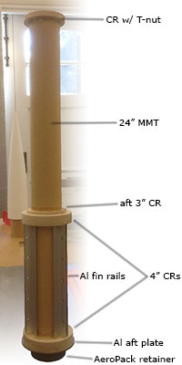
There was no room for dual deployment (and I couldn't break the main aiframe because of the LED strips), so the electronics bay had to go into the nose. After that long preamble, that here is the overall drawing.
I have to give a big thanks to the members of AERO-PAC, and in particular to Paul Campbell, for answering my stupid electronics questions.
Body Core
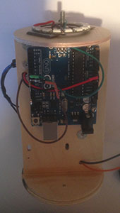
From the overall drawing you can see how much room was taken up by the battery sled to power all those LED strips. The battery sled was cut from 6mm baltic birch plywood, with parts that fit together like a puzzle.
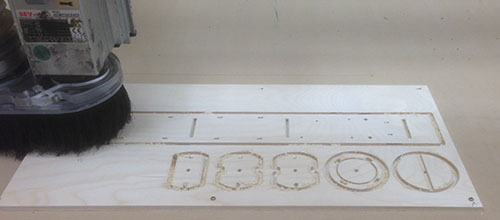
Above you can see the parts being cut out on a ShopBot CNC router at my local TechShop. And below you can see the battery slide put together and bonded with epoxy.
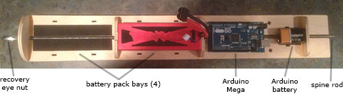
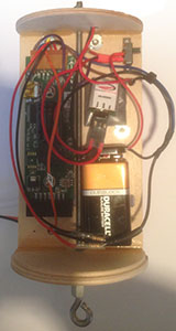
The four battery packs fit tightly into the bays and are retained with large tie wraps, the Arduino is mounted using stand-offs through its pre-drilled holes and the 9v battery is also mounted with a smaller tie wrap. The central spine rod threads into a centering ring at the aft end of the 3" central section and has an eye nut on the top for the recovery harness.
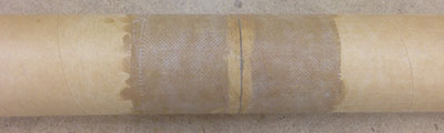
The 3" core tube is 56" long, much longer than available lengths of phenolic tubing, so I had to join two sections of 36" tubing together. Normally one would do this using a coupler, but since I needed the inside to be clear for the entire length, I used a wrap of 6oz fiberglass to make an outer coupler.
Other than that, the main body is pretty simple: just a long 3" tube. At the aft end end, the fin can is built around the 54mm motor mount, which then slides into the core tube. (See below for more on the fin can.)
 |
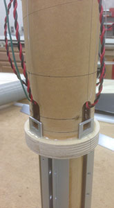 |
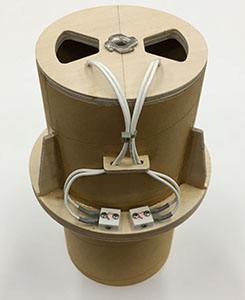
Above left you can see how the wiring for the LED strips goes through the forward centering ring/bulkhead on the motor mount tube so that it can feed out at the aft end of the 3" core tube. Four power wires (red/black) and one signal wire (green), plus fishing line through each hole in case I need to run more wires later.
Above right the fin can/MMT has been installed into the core tube and the wires brought out through slots on the outside. The small aluminum rectangles are plates for switches that control the power fed to the light strips (one per power feeder, for five strips).
Once the body construction was complete, the only painting was done; I sprayed flat black over the area which would be covered with LED pixel strips. Then it was time to start mounting the strips themselves.
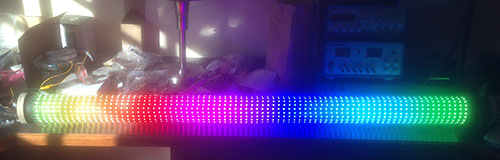
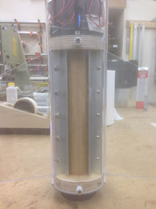
The strips had an adhesive backing, so I used that to apply them longitudinally (20 strips, 18° apart). In the picture above, all twenty strips are on and wired up. Things things are bright; that's in a fully lighted room!
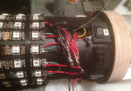
Above is the wiring for those first five strips (the 'A' bus on the first of the four LiPo packs). It's a bit messy, but I'll neaten it up once the whole thing is wired and working. As for the soldering, what can I say, I'm a software guy.
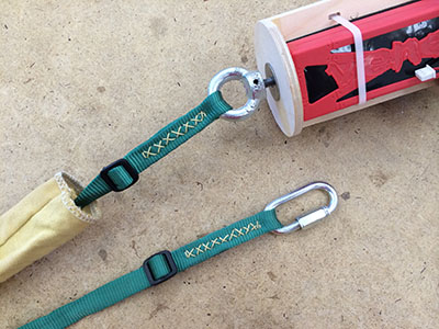
Above you can see how the main bridle attaches to the eyebolt at the front of the bay. The eyebolt actually turns within the sled so the aft end of the threaded rod can screw into the bulkhead at the forward end of the MMT.
Fin Can
I wanted the fins to be clear also, so they were cut from 3/16" polycarbonate sheet. That worked out well, but of course they could not be bonded to the tube, so I had to use aluminum angle to make rails they could bolt to.
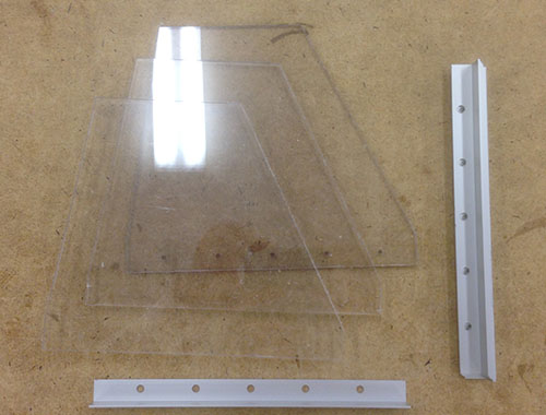
The rails were bonded to the outside of the 54mm motor mount tube, and also the ends socket into slots cut into the centering rings. These centering rings were actually cut from ¾" plywood, much thicker than usual, so that I could mount threaded inserts into them for attaching the clear outer tube.
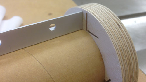
Above you can see how the aluminum rails ends slide into slots machined ¼" into the extra-thick centering rings. A pair of rails holds each fin in place. Below you can see the completed fin can built on the 24" motor mount tube.
The forward half of the motor mount assembly slides into the 3" core airframe tube. (See the overall drawing, or above for more on the body core.)
 |
 |
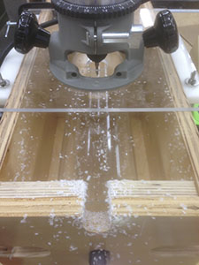
The final bit of construction was to slot the Acrylic outer tube for the fins. I did this using my trusty fin slotting router jig. And finally, in the above right photo, you can see the aft end of the rocket completed.
Nose And Electronics Bay
There was no room for dual deployment, so I decided to place the electronics bay into the nose. This bay does dual duty for lighting the nose and containing the recovery electroncs.
The nose cone shoulder didn't, of course, work with the outer Acrylic tubing, so I cut it off and built the electronics bay into a 3" coupler that would slide into the core phenolic airframe tube.
The top (forward end) of the bay inside the nose cone is actually an acrylic plate, which allows lights at the top of the sled to shine through and illuminate the nose. So in addition to an altimeter, there's also an Arduino Uno to drive a ring of LED pixels in this bay.
There was a lot to pack into this small bay: an R-DAS and an Arduino Uno, not to mention the 9v battery and all the various wiring.
 |
 |
Above you can see the bay with both sides populated. On the left is the altimieter side with the R-DAS and battery, plus the 5v regulator for the pixel ring on top. On the right is the Arduino side, and on the top you can see the ring of 16 LED pixels.
Animation
All that stuff above is just to create the canvas for the "light show" itself! Those 20 strips of 80 pixels create a grid of 1600 pixels that I had to paint in some interesting way. Of course, one can only see about half of them at a time when wrapped around the rocket, so that means a relatively simple moving design works best.
Plus the Arduinos, even the Mega, have a relatively limited amount of memory, so it's not realistic to use video as the source. What I ended up choosing was a rainbow that traveled up (down) the rocket body, which provides a colorful undulating design. (More complex patterns were too much for the Arduino to handle since addressing 1600 individual pixels takes time).
Despite its limitations, the Arduino is an easy platform to work with. Above you can see me with the computer connected to the rocket, tuning the timing of the animation and watching the results almost instantly.
Prepping the Rocket
Because I wanted the LED strips to be uninterrupted, it made for a difficult-to-prep rocket. Not only could I not easily do dual-deployment, but everything had to go in from the front end, meaning there was excess wire to manage.
Those of you would would like to see the details of prepping this rocket can suffer through it with me in the video above. It ends with the rocket lit up at night, so there is eventually a "light show," although the LEDs are so bright the effect isn't nearly as good on video as in person.
Version 2
Things I learned from the first version:
- These lights, especially in this quantity, are incredibly bright.
- The nose cone lighting up isn't visible.
- There's no point in clear fins or a clear tail section.
- A faster processor and refresh rate is necessary for complex patterns.
- There's no need for such a long motor mount.
Since nothing can be seen other than the main light column, the nose would not be lighted and the tail section would be normal rocket construction. Both nose and tail would be painted black.
I also decided to increase the inner tube from 3" to 3.9", using a 5.5" O.D. clear tube and matching Blue Tube airframe for the aft section. The larger diameter means the number of pixel columns could increase, even up to 30. I decided to go with 24 columns, which was the closest circumfrential spacing to the longitudinal spacing of the pixel strips. That's 24 rows of 75 pixels each, for a total of 1800 individual lights.
The Arduino line is still pretty much the same as 2013, but there are other options for processors. This time I decided on the Teeny 3.6, which has a much faster clock rate and even a floating-point coprocessor.
Since I built version 1, a new generation of LED pixel strips became common. The APA102-C strips can be addressed much faster because they use a 2-wire SPI protocol rather than the fixed-rate 1-wire protocol of the older WS2812B strips. These can be purchased from AdaFruit under the name "DotStar", or from Amazon or Alibaba in full 5m reels.
So a faster processor and faster-updating strips meant that some of the original ideas I had for the lighting effect were now practical. See the various ideas on the right, based on a rainbow with different animation patterns.
Finally, the original 24" 54mm MMT was overkill since you can't fly that high at night anyway. The most likely motors are large Js for the AeroTech RMS-54/1280 case, which is only 12" long. (I flew version 1 on an J415).
In late November 2017 I started ordering parts:
- BlueTube airframe from Always Ready Rocketry,
- polycarbonate tube from Profressional Plastics,
- Teensy 3.6 from SparkFun Electronics,
- and pixel strips from Amazon.
The rest would be stuff I had laying around or purchased locally.
Redesign
See the v2 overall drawing for details, but more interesting is the comparison with v1:
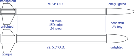
So the new one is shorter, fatter and simpler. The inner tube on which the light strips are mounted is a 3.9", instead of a 3", airframe. But mainly I'm going to make sure the rocket is a lot easier to prep, with redundant electronics and no excess wire.
To achieve the less wire, the center section with the lights removes from the aft end and center core. The body tube with the pixel strips slides over the core and power connectors are used after installation. This means the switches are mounted on the aft section and the wiring runs only over pieces that are bonded together, allowing me to remove slack.
Again the recovery bridle would be anchored to the core (and ultimately to the motor).
Electronics
For those looking to use light strips, the APA102-C strips can be addressed much faster because they use a 2-wire SPI protocol rather than the fixed-rate 1-wire protocol of the older WS2812B strips. These draw about 10A maximum (all white, full brightness) per strip of 300 pixels at 5V.
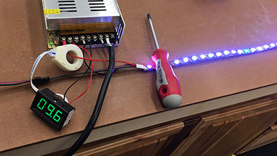
For the rainbow patterns I plan to use, the current draw is more like 3A (measured 2.8A). This means I can power two strips from a 10,000MAh NiMH battery (10A continuous). The advantage of NiMH batteries is that at 4.8V, I don't need to use a voltage regulator.
It also turns out that even though the Teensy's outputs are 3.3V, that's enough to control the pixel strips. The strips regenerate the signal at each pixel, so the Teensy only has to control the first one. There are step-up boards to raise the 3.3V signal to 5V, but I didn't need to use them.
The Teensy is programmed in C just like the Arduinos and in fact even uses the same Arduino IDE to do so. See the "Teensyduino" package which adds support to the Arduino IDE. I used the FastLED library, which comes bundled with Teensyduino, to control the pixels. Not only does this handle many different kinds of light strips, it also has higher-level functions such as HSL color conversion.
The Teensy is not the same form factor as any of the Arduinos, so none of the shields will work. It also doesn't come with any mounting holes, so other arrangements must be made. I did find a break-out board with mounting holes, but soldering directly to the Teensy is easy and a custom fixture can be made to mount it.
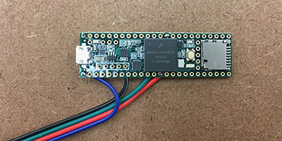
Above you can see the four connections needed to drive the pixel strips: +5V, ground, SPI data on pin 11, and clock on pin 13. (Ignore the wire colors; the connector that came with the LED pixel strip doesn't use a familiar scheme.)
Aft Section
The aft section is basically just a fin can. The only complexity comes about forward of the motor where the electronics are mounted and on the bulkhead just forward of the fins where the inner tube with LEDs and the outer clear tube mount for flight.
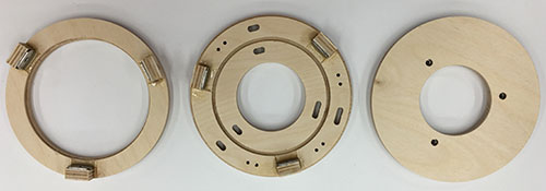
The rings have to support the MMT, center the inner light tube and slide into the outer body tube. Above you can see the forward, mid and aft centering rings. The forward and mid rings have tabs to which the outer plastic tube will attach. The groove in the mid ring is for a 3.9" coupler section to which the inner light tube will attach. The aft ring is simple, with only the MMT running through it.
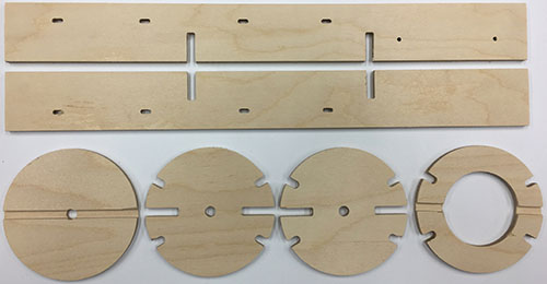
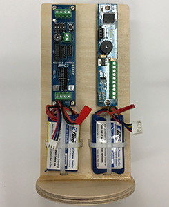
The battery sled was once again a major part of the structure. Above you can see the parts cut out and below the way they lock together to create the core which holds the batteries and Teensy computer.
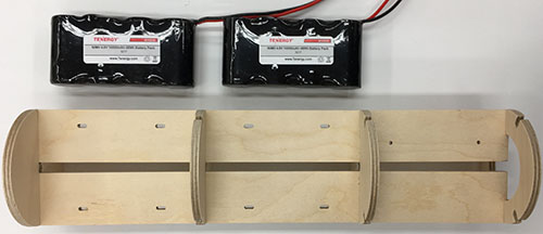
Two of the three batteries are shown next to the dry-fit sled to show how each one will have its own compartment and be strapped in with zip ties. The third section, on the right, is for the Teensy computer. A 5/16" threaded rod runs through the center, anchoring to the 54mm motor hardware at the aft end and supporting an eye nut at the forward end for recovery.
Nose
Once again, the avionics bay would be in the nose. But this time it's based on a 3.9" coupler 8" long so I have enough space for redundant electronics. I am also not trying to run another light in the nose so things are simpler should be more reliable.
 |
 |
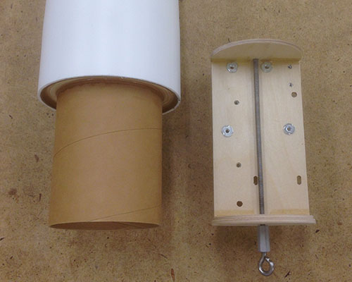
Above left you can see the core that fits into the Loc/Precision plastic nose cone after cutting off the molded shoulder. And on the right the electronics bay plate which slides into the core from the aft end. The tube forming the core is a 3.9" coupler tube, so it naturally mates with the 3.9 inner airframe, even though the outer diameter is 5.5".
The usual ¼" threaded rod provides the attachment point for the ebay within the nose core.