Astrobee 500
In 2018, I was complaining about my lack of time to attend launches and dislike of painting with William Wallby. (When I moved shops, I lost my paint booth, which made the latter worse.) He suggested we do a join project where I do the building and he the painting and flying, and he suggested the Astrobee 500 as an interesting subject.
The Pictures
The Design
The first question with a scale model is always the scale. Since it's easiest to base it around available body tubes, we decided that 25% scale gave a good overall size of 76" (1.94m) and second and third stages that matched 5" and 54mm airframe tubing. The first stage didn't match well, but making it slightly oversized using a 3.9" coupler tube would still give the right feel.
| Prototype (in) | Model (in) | |
|---|---|---|
| 1st stage ϴ | 15.0 | 3.75 |
| 1st stage len | 62.0 | 15.50 |
| 1st stage span | 72.0 | 18.00 |
| 2nd stage ϴ | 20.3 | 5.08 |
| 2nd stage len | 76.4 | 19.10 |
| 2nd stage span | 52.0 | 13.00 |
| 3rd stage ϴ | 6.5 | 1.63 |
| 3rd stage len | 167.5 | 41.88 |
| overall len | 306.0 | 76.50 |
The third stage had an aft cone (no fins). The first stage body is substantially shorter because the aft end is a large nozzle. Here's the usual overall drawing.
This rocket is pretty large, but has both little space for motors and little recovery space. Because of the nozzle, only a 38mm MMT works in the booster. While a 3" MMT might fit into to the second stage, there is more selection in the appropriate length in 54mm motors (plus this accomodates an electronics bay alongside the MMT). Of course the third stage is a 38mm minimum-diameter.
Construction
Construction followed my now-standard techniques of using phenoic body tubes, plywood bulkheads and centering rings and carbon fiber plate fin cores with 3D printed profiles. 3D printing continues to take more prominence in this rocket, forming structures that I would have have made from foam and fiberglass before.
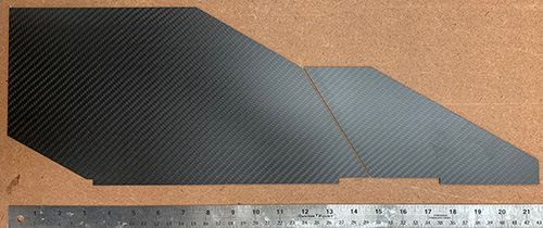
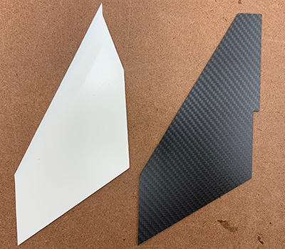
Above you can see the two fin cores positioned as they will be when the rocket booster and second stage are stacked up. These were cut from 1.5mm carbon fiber plate and the profiles will be built up from 3D printed edges and balsa.
Since there is so much going on in this rocket, I need to keep the alignment of everything organized. To do that, I marked a line down all body tubes and on all centering rings along the rail guides (back of the rocket). All structures were laid out around this line.
Booster
The booster has a short 38mm MMT. It is dominated by the massive fins of this prototype. The fins are so large that I didn't print the profile completely, but only printed the leading edge with the bevel detail and filled in the body of the fins with balsa to save weight. Here is a detailed drawing of the booster.
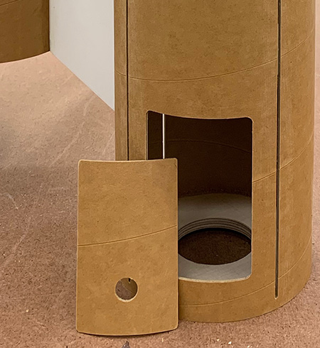
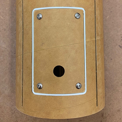
Most likely, the booster will be recovered with motor ejection, but I added a small electronics bay at the aft end just in case. In the past I would have done this using using a router, but this time I decided to use the cutout as the hatch cover and fill the space cut away and use a 3D printed ring to fill in the back.
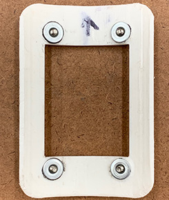
The plastic ring is backed by #4-40 weld nuts epoxied in place to hold the screws to retain the hatch cover.
 |
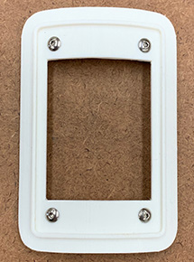 |
This produces a clean result the hatch also allows access for internal fillets aft end of the booster, which otherwise would be blocked by the centering rings.
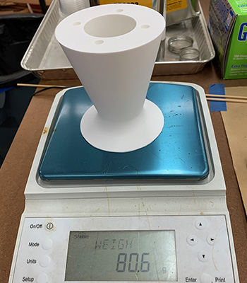
The other fun detail at the aft end is the nozzle. I decided to 3D print this, to save weight, and it ended up being only 81g (2.9oz), which is pretty good for this large sized piece.
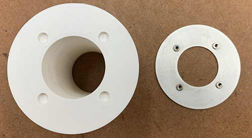
The aft end of the nozzle is capped with a piece of 1/16" thick aluminum. This protects the aft end of the nozzle, plus provides a solid mount for #6 PEM nuts for the motor retainer. (The nozzle was printed in ABS, but the aluminum will still be stronger and more heat-resistant.)
The aluminum plate was bonded onto the aft end of the nozzle and the MMT is recessed just enough that the aft closure lip is flush with the aft end of the complete nozzle.
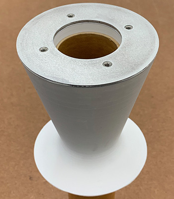
Above you can see how the phonolic MMT is recessed to transfer the thrust to the airframe. The motor is enclosed by the printed nozzle, but does not touch it directly. Below you can see how the motor fits into the nozzle, closure flush with the aft surface.
And finally the motor retrainer is another piece of 1/16" aluminum plate, mounted with screws that thread into the PEM nuts in the aft plate of the nozzle.
This is intended to be low-profile, to hide the booster motor as much as possible from the side when the rocket is on the pad.
Second Stage
The second stage has a longish 54mm MMT. It is the largest in diameter and has smaller fins that align with the massive booster fins. Since this stage needs to be air-started, it has accomodation for aft-end ignition and even support for dual electronics bays tucked into the aft end around the MMT. Here is a detailed drawing of the 2nd stage.
I started building this first because it's the most interesting. Around the MMT is a sleeve of 3.9" coupler tube that forms the aft body. The main body is formed of 5.4" blue tube
This is most of the interesting part of the rocket. On the left is the MMT with the various rings. In the center is the aft end sustainer body and on the right is the blue tube main body. If you look carefully, you can see the aluminum tubes for threading the staging igniter(s) up to the electronics bay at the aft end of the main body. You can also see the slots for the through-the-wall fin tabs.
Above is an aft-end view of the MMT assembly and aft body. Note that the very after centering ring is smaller in diameter, which accomodates the coupler on the booster, and ends in an aluminum thrust plate.
The profiles are quite thick with a taper at the forward edge. They are also notched out where the transition pieces will fit betwen the fins (see below).
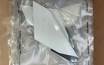
The 3D printed profiles were epoxied to the cores and then held together using the FoodSaver vacuum bagging method.
![]()
The fins were bonded in two phases. The aft end of the fin tab was bonded between the two inner centering rings, inside the aft body. Then, the four transition pieces were bonded in to lock the forward ends of the fins in place.
Third Stage
The third stage is a minimum diameter 38mm rocket with a cone instead of individual fins. Just enough space is left for the long-burning AeroTech I59. Even though this stage is pretty long, 38mm doesn't leave much space inside. Here is a detailed drawing of the 3rd stage.
Historical Info.
From Rockets of the World, 3rd edition (page 191):
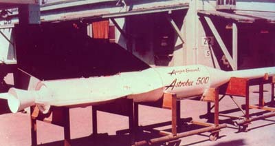
In the early 1950's, Aerojet General was America's premier builder of sounding rockets, producing the famous Aerobee line of liquid-fueled sounding rockets. But in the mid-50s, solid-fueled rockets, such as the Nike-Deacon and Nike-Cajun became attractive, economical competitors. In 1958, Aerojoet entered the solid rocket field with its Astrobee 75, but with limited success. In 1959, Aerojet tried again, introducing the first members of a new line of solid propellant rockets: the Astrobees. The first of these to be tested was the Astrobee 500.
The Astrobee 500, deployed for the Air Force Cambridge Research Laboratory (AFCRL), was a 3-stage rocket capable of carrying a 15lb (7kg) payload to an altitude 765 miles (1,224 km), or a 40lb (18kg) payload 600 miles (960 km).
The Astrobee 500 was launched from a rail launcher under the power of a high-thrust MB-1 booster. Its 2-second burn was followed by a 12-second coast, as the upper two stages cleared the densest layers of the atmosphere. Then the second stage ignited for its 30-second burn. The third stage was an Asp sounding rocket, its fins replaced by a stabilizing cone at the rear. Aerojet offered an option for attitude control to precisely orient the payload as it collected data.
The AFCRL ordered two Astrobee 500's, and on March 22, 1960, one was launched from the Air Proving Ground Center in Florida. The vehicle was to release "poppy" flares at altitude. These would act as beacons for geodetic triangulations by ground observers. But an unspecified failure of the launch vehicle ruined the experiment.
There is no record of a second attempt, but the end of the Astrobee 500 signalled the beginning of a whole series of Astrobee rockets. By the next year the Astrobee 200 and Astrobee 1500 were flying.